

In this series i’ll document how I put together a lot of people’s hard work into a home control center that is based off the raspberry pi, both for my future reference and for anyone out there who needs to build something similar. By the end of it, we should be able to have the following features:
- Monitor temperature and humidity across various points in the house – wirelessly
- Connect to your network via wireless
- Display essential info on an OLED screen
- Have a “webcam” mode that will allow you to stream real-time video of a room in your house wherever a raspberry pi is installed
- Have a “security mode” that will record about 30-60 seconds of video everytime movement is sensed wherever a raspberry pi is installed
- Trigger alarms whenever movement is sensed or doors open/close – wirelessly
- Have an easy to use WEB UI that also works on your mobile phone
- Can control lights on sensing movement
That’s quite a list which I hope to eventually complete and document. In this 1st part, I’ll focus on:
- Connect to the network via wireless
- Display IP address, local temperature and humidity on an OLED screen
Most of the heavy lifting has been done by the awesome folks over at www.adafruit.com , in most cases I was just gluing everything together…. This guide assumes a fresh raspbian install (preferably via NOOBS). Without further ado
- Connect to the network via wireless
Really simple and run of the mill – if you have the right hardware. This point is key… I’ve had other wireless cards and they involved compiling drivers, not working, rinse, repeat. Save yourself a lot of hassle and just get a wireless USB that works out of the box. The adafruit one is perfect:
http://www.adafruit.com/products/814
Simply switch off your raspberry pi, plug it in and wait for a bootup and run an ifconfig to make sure wlan0 is listed. Then it’s the usual connect-your-linux-to-wlan procedure… In my case, I am connecting to a WPA2, pre shared key wireless lan. First add the following to your /etc/network/interfaces file:
allow-hotplug wlan0
iface wlan0 inet manual
wpa-roam /etc/wpa_supplicant/wpa_supplicant.conf
iface wlan0 inet static
address 192.168.1.245
netmask 255.255.255.0
network 192.168.1.0
gateway 192.168.1.1
ctrl_interface=DIR=/var/run/wpa_supplicant GROUP=netdev
update_config=1
network={
 ssid="YOUR_WLAN_SSID"
 proto=RSN
 key_mgmt=WPA-PSK
 pairwise=CCMP TKIP
 group=CCMP TKIP
 psk="YOUR_PASSWORD"
}
Once again amend as necessary. I also added the following to the /etc/rc.local file to make sure the wireless connected on bootup:
ifdown --force wlan0
ifup --force wlan0
That’s it for wireless.
- Display IP address, local temperature and humidity on an OLED screen
The OLED screen purchase and setup were a breeze thanks to adafruit. Visit and follow the tutorial here: http://learn.adafruit.com/adafruit-oled-displays-for-raspberry-pi.
The author of this post already includes how to display IP addresses on the OLED screen in one of his python examples so you’re halfway there. Adding the temperature and humidity are equally easy, again due to adafruit’s amazing tutorials. In this case, follow the one here: http://learn.adafruit.com/dht-humidity-sensing-on-raspberry-pi-with-gdocs-logging/overview
I obviously did deviate here since I wanted to place the information on the OLED screen rather than google docs. So in my case, after performing this step:
$ git clone git://github.com/adafruit/Adafruit-Raspberry-Pi-Python-Code.git
$ cd Adafruit-Raspberry-Pi-Python-Code
$ cd Adafruit_DHT_Driver
I compiled and installed the python library for the DHT driver as follows:
cd ../Adafruit_DHT_Driver_Python
python setup.py build
This results in a dhtreader.so file in the build directory which we can now use directly in python. Next to code:
- Create a directory for the project. In my case:
mkdir /home/pi/raspiCC
- Create a new python file and copy/paste the following:
This file contains hidden or bidirectional Unicode text that may be interpreted or compiled differently than what appears below. To review, open the file in an editor that reveals hidden Unicode characters.
Learn more about bidirectional Unicode characters
| #!/usr/bin/env python | |
| # -*- coding:utf-8 -*- | |
| # Meant for use with the Raspberry Pi and an Adafruit monochrome OLED display! | |
| # This was coded by David Vassallo, modified from code by The Raspberry Pi Guy | |
| # Imports all of the necessary modules | |
| import gaugette.ssd1306 | |
| import time | |
| import sys | |
| import socket | |
| import fcntl | |
| import struct | |
| from time import sleep | |
| import dhtreader | |
| import cPickle as pickle | |
| # IMPORTANT – YOU MAY NEED TO CHANGE THIS PART!!!!! | |
| # Sets our variables to be used later | |
| # CHANGE THE BELOW IF YOU ARE NOT USING A DHT22 but some other model | |
| DHT22 = 22 | |
| dev_type = DHT22 | |
| # CHANGE THE BELOW IF YOU ARE USIG A DIFFERENT GPIO PORT FOR THE DHT SENSOR | |
| dhtpin = 23 | |
| # SGHOULDNT BE CHANGED UNLESS YOU WIRED THE OLED SCREEN DIFFERENTLY TO THE ADAFRUIT GUIDE | |
| RESET_PIN = 15 | |
| DC_PIN = 16 | |
| # This function allows us to grab any of our IP addresses | |
| def get_ip_address(ifname): | |
| s = socket.socket(socket.AF_INET, socket.SOCK_DGRAM) | |
| return socket.inet_ntoa(fcntl.ioctl( | |
| s.fileno(), | |
| 0x8915, # SIOCGIFADDR | |
| struct.pack('256s', ifname[:15]) | |
| )[20:24]) | |
| led = gaugette.ssd1306.SSD1306(reset_pin=RESET_PIN, dc_pin=DC_PIN) | |
| led.begin() | |
| led.clear_display() | |
| for i in range (0,5): | |
| textTempHeader = "Temperature:" | |
| textHumidHeader = "Humidity:" | |
| try: | |
| dhtreader.init() | |
| temp, humid = dhtreader.read(dev_type,dhtpin) | |
| with open('/home/pi/flask/sensors.pickle', 'w') as f: | |
| pickle.dump([temp, humid], f) | |
| temp = "{} *C".format(temp) | |
| humid = "{} %".format(humid) | |
| except: | |
| temp = ('No Reading!') | |
| humid = ('No Reading!') | |
| # The actual printing of TEXT | |
| led.clear_display() | |
| led.draw_text2(0,0,textTempHeader,1) | |
| led.draw_text2(0,8,temp,1) | |
| led.draw_text2(0,16, textHumidHeader, 1) | |
| led.draw_text2(0,25,humid,1) | |
| led.display() | |
| sleep(9) | |
| led = gaugette.ssd1306.SSD1306(reset_pin=RESET_PIN, dc_pin=DC_PIN) | |
| led.begin() | |
| led.clear_display() | |
| try: | |
| TEXTwlan = get_ip_address('wlan0') | |
| except IOError: | |
| TEXTwlan = ('NO WIRELESS!') | |
| try: | |
| TEXTlan = get_ip_address('eth0') | |
| except IOError: | |
| TEXTlan = ('NO INTERNET!') | |
| # The actual printing of TEXT | |
| led.clear_display() | |
| ipWLAN = 'Your WLAN IP Address:' | |
| ipLAN = 'Your LAN IP Address:' | |
| led.draw_text2(0,25,TEXTlan,1) | |
| led.draw_text2(0,8,TEXTwlan,1) | |
| led.draw_text2(0,0,ipWLAN,1) | |
| led.draw_text2(0,16, ipLAN, 1) | |
| led.display() | |
| sleep(9) |
If you notice, in the above code I’ve placed the main logic in a for loop with specific sleep periods. This was done so the whole script executes for a total of just under 60 seconds. This way, we can schedule a cron job that runs every minute and will continuously cycle between IP and environment information. This is quite simply done via first entering
sudo su -
crontab -e
Then entering the following crontab entry:
* * * * * /home/pi/raspiCC/daveOLED.py
The above will run our script every minute and refresh our OLED display. Here are the results so far:

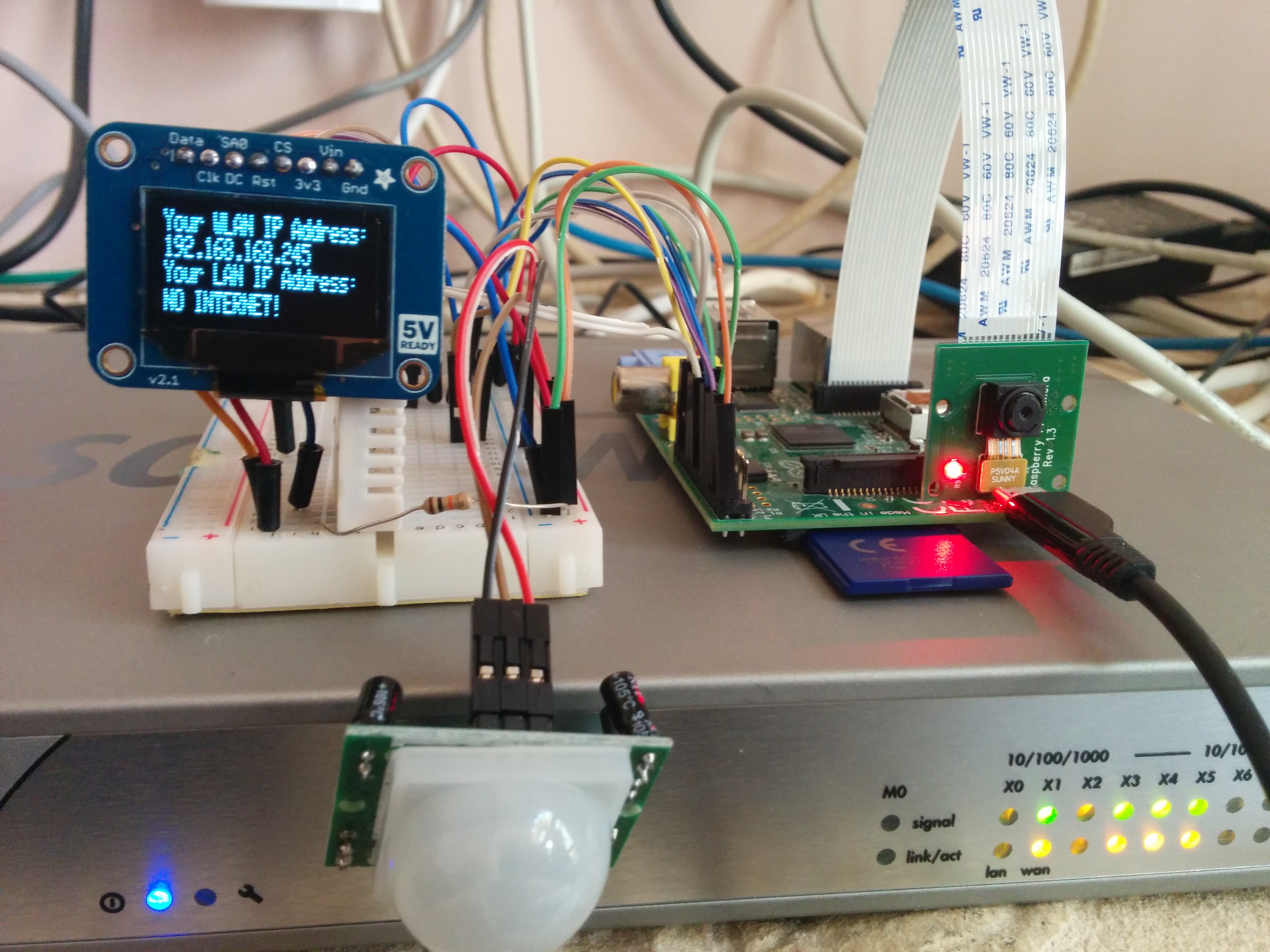
Note the camera and infrared sensor in the last photo, which is coming up next… connecting the raspi cam to record about 30-60 seconds of video everytime movement is sensed near your pi 🙂

2 thoughts on “Raspberry Pi : Home Control Center Part 1”